
Current location: HOME > BLOGS > Frequently Asked Questions >
Professional Photovoltaic Cable Installation Guide for Solar Systems
time:2026-07-02 08:46:16 author:haoshizai Click:107
Installing photovoltaic cabling requires precision engineering and adherence to electrical codes designed specifically for solar energy applications. Whether setting up a residential rooftop array or a commercial solar farm, proper installation directly impacts system performance, longevity, and safety. This guide walks through essential practices that distinguish professional solar installations from amateur efforts.
Pre-Installation Planning and Site Assessment
Before any physical work begins, thorough planning prevents costly corrections during installation. Calculate total system wattage, accounting for panel efficiency losses and future expandability. Map cable routes, identifying potential obstacles and environmental exposures. Consider conduit requirements—underground runs face different challenges than above-ground installations exposed to weathering.
Cable sizing calculations using standard electrical formulas ensure appropriate conductor gauges match current draw. Voltage drop calculations become especially critical for longer runs between array locations and inverter connections. Professional installers use software modeling to optimize route efficiency before committing to materials.
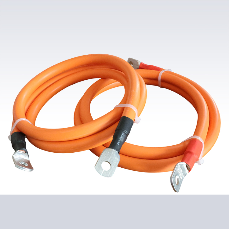
Selecting Appropriate Photovoltaic Cables
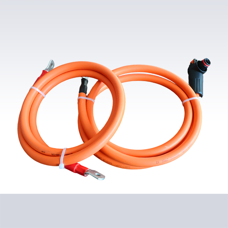
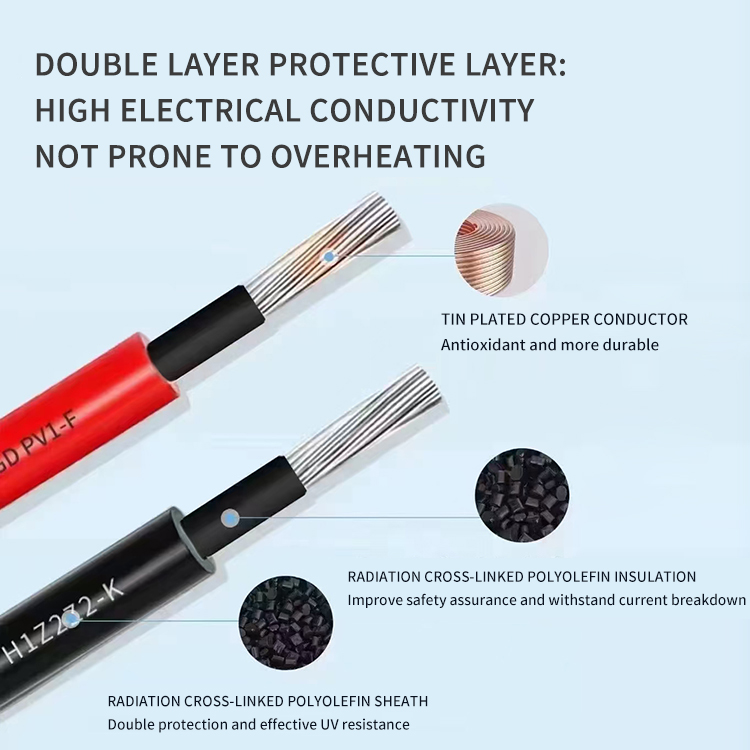
Not all cables labeled for solar use meet the demands of permanent outdoor installation. True photovoltaic cables feature cross-linked insulation resisting UV degradation, extreme temperature fluctuations, and moisture ingress. Confirm certifications meet local electrical codes—the National Electrical Code specifies particular standards for solar interconnect wiring.
DC-rated cables区别于 standard AC wiring—their insulation holds up under direct current stress that AC cables cannot handle reliably. Factory-manufactured PV cables undergo accelerated aging tests simulating decades of outdoor exposure. Sourcing from established suppliers guarantees stated ratings match actual performance.
Routing and Conduit Techniques
Routine best practices preserve cable integrity throughout the system lifetime. Maintain minimum bend radii—typically 8 times cable diameter—to prevent conductor stress and jacket damage. Support cables adequately along horizontal runs, typically every three feet in vertical drops.
Conduit use prevents rodent damage and accidental physical impact. For underground installations, schedule 40 PVC or rigid metal conduit provides necessary protection. Depth requirements vary by jurisdiction, generally requiring 18-inch cover for residential circuits. Pull boxes at junctions facilitate future modifications without disturbing completed runs.
Grounding and Bonding Requirements
Proper grounding protects equipment and personnel from lightning-induced surges and fault conditions. SOLAR systems require dedicated grounding conductors sized per NEC Table 250.122, connecting metal enclosures, panel frames, and mounting rails to ground electrodes.
Bonding ensures all metallic components maintain equipotential, preventing shock hazards during maintenance. Equipment grounding conductors run alongside circuit conductors, connected at each junction point. Verify ground resistance readings below 25 ohms using appropriate earth ground testers after installation completes.
String Configuration and Series Connections
Panel string arrangements determine system voltage and current parameters. Series-connected panels increase voltage while parallel strings add current capacity. Modern inverters accept specific input windows—matching your configuration prevents efficiency penalties or inverter damage.
String combiners simplify wiring for larger arrays, combining multiple string outputs before inverter connection. Properly fusing each string protects against reverse-current damage during partial shading or panel failures. Document string assignments clearly for ongoing maintenance access.
Testing and Commissioning Procedures
Systematic testing validates proper installation before energization. Megohmmeter insulation testing confirms jacket integrity—readings below acceptable thresholds indicate damage requiring correction. Continuity testing verifies correct conductor connections throughout the system.
Polarization tests ensure positive and negative circuits maintain proper polarity through all connections. Pre-energization checklist verifies all connections are tight, all covers are secured, and all tools are removed from the work area. Document test results for warranty compliance and future reference.
References
National Electrical Code (NEC)Article 690: Photovoltaic Systems
UL 4703: Standard for Photovoltaic Wire
IEC 62930: Photovoltaic Cables for Rooftop and Other Applications
NECA 230: Standard for Installing Wire and Cable
Solar Energy Industries Association (SEIA) Installation Guidelines