


Current location: HOME > BLOGS > Frequently Asked Questions >
Solar Cable Installation Best Practices for Long-Term Performance
time:2026-08-25 06:31:40 author:haoshizai Click:96
Installing solar panels involves more than mounting hardware and connecting wires. How cables run between panels, across rooftops, and into junction boxes significantly impacts system reliability. Poor cable installation leads to premature failures, safety hazards, and costly repairs that could have been avoided with proper technique.
Planning Cable Routes Before Installation
Walking a site before installation reveals routing challenges that aren't obvious from architectural plans. Obstacles like HVAC equipment, skylights, and drainage systems force cables into paths that might expose them to damage or create trip hazards for maintenance personnel.
Experienced installers sketch cable routes on paper first, noting total lengths and any sections requiring protection. This planning phase identifies where longer cables or additional conduit might be needed. A supplier who understands installation requirements can recommend optimal cable lengths to minimize splices and junction boxes.
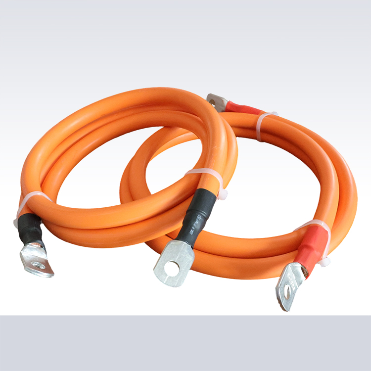
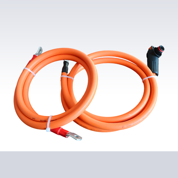
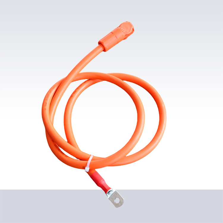
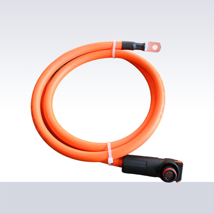
Factory pre-assembly of cable assemblies reduces on-site labor time. When cables arrive with connectors already attached and measured to specified lengths, installation crews work faster with fewer errors. The cost premium for pre-assembly typically pays for itself in reduced installation time.
Proper Cable Support and Strain Relief
Cables hanging freely between panels eventually fatigue from wind-induced movement. The constant flexing concentrates stress at connector junctions, leading to contact degradation and potential failure points. Proper support eliminates this mechanical stress.
Cable clips designed for photovoltaic applications attach to module frames or mounting rails. These clips hold cables securely without crushing insulation. Quality clips feature UV-resistant materials that won't become brittle after years of sun exposure. A manufacturer providing compatible clips with cable orders ensures proper fit and material quality.
Service loops at connection points allow for thermal expansion and future maintenance. Cables expand and contract with temperature changes. Without slack, this movement stresses connectors. Leaving 6-12 inches of extra cable at each termination point provides flexibility for component replacement without resplicing.
Weatherproofing Connection Points
Every cable connection represents a potential entry point for moisture. Water ingress causes corrosion, increases resistance, and can lead to arc faults. Proper weatherproofing protects these vulnerable points throughout the system's operational life.
MC4 connectors include sealing glands that compress around cable jackets. Correct installation requires matching gland size to cable diameter. An undersized gland won't seal properly; an oversized one won't grip securely. Factory-crimped connectors eliminate the guesswork involved in field assembly.
Junction boxes need IP65 or better ratings for outdoor locations. The cable entry points into these boxes require cable glands rated for the cable diameter and environmental conditions. Some installers apply silicone sealant around gland fittings as additional protection, though properly rated glands should suffice.
Avoiding Thermal and Electrical Issues
Cables bundled together share heat, which can push temperatures beyond insulation ratings. When multiple cables run in conduit or raceways, derating factors apply. A cable rated for 40 amps in free air might only handle 32 amps when bundled with several others.
Manufacturers provide derating tables in their cable specifications. These tables account for different bundle sizes and installation methods. Ignoring derating factors leads to cables running hotter than designed, accelerating insulation aging and reducing service life.
Keeping cables away from heat sources seems obvious, but rooftop installations sometimes position cables near exhaust vents or air conditioning units. The heat from these sources adds to solar heating, potentially pushing cable temperatures beyond their rated operating range.
Grounding and Bonding Requirements
Proper grounding protects against electrical shock and equipment damage. The grounding conductor must run continuously throughout the system, connecting all exposed metal parts to a common ground point. Cable manufacturers often include a separate grounding conductor in their products or recommend appropriate grounding wire sizes.
Equipment grounding conductors need to handle fault current until protective devices trip. Undersized grounding conductors might not carry enough current to trip breakers quickly, leaving faulted equipment energized. Factory guidance on grounding requirements helps ensure compliance with electrical codes.
Some installations use the cable armor or conduit as the grounding path. This approach requires careful attention to bonding at every joint and termination. A supplier offering cables with integrated grounding conductors simplifies this aspect of installation.
Labeling and Documentation
Future maintenance depends on knowing which cables serve which circuits. Clear labeling at both ends of each cable run saves time during troubleshooting. Weatherproof labels or engraved tags resist degradation from outdoor exposure.
As-built documentation showing actual cable routes differs from original plans in most installations. Recording these differences creates accurate records for future reference. Some installers photograph cable routes before covering them, providing visual documentation alongside written records.
Factory documentation should include cable specifications, testing records, and installation recommendations. A manufacturer who provides comprehensive documentation supports installers in meeting code requirements and quality standards.
Testing and Commissioning
Before energizing a new installation, testing verifies cable integrity. Insulation resistance testing identifies damage that might not be visible externally. A megohmmeter applies high voltage between conductors and ground, measuring any current leakage.
Polarity testing prevents reversed connections that could damage equipment or create safety hazards. This simple check using a multimeter takes minutes but catches a common installation error. Continuity testing verifies that connections are sound throughout each circuit.
Factory test reports for cables provide baseline measurements. Comparing field test results against factory data identifies any degradation that occurred during shipping or installation. A supplier who maintains detailed test records supports quality verification throughout the supply chain.
References
National Fire Protection Association. NFPA 70: National Electrical Code. Quincy: NFPA; 2023.
North American Board of Certified Energy Practitioners. NABCEP Photovoltaic Associate Study Guide. Clifton Park: NABCEP; 2022.
Solar Energy Industries Association. Solar Installation Best Practices Manual. Washington: SEIA; 2021.






CONTACT
Email:525860526@qq.com
Whatsapp: +86 19933450664
TEL:+86 17803069333
WEB:https://www.haoshizai-solar.com
ADD:Dongyang Village, Daweihe Hui and Manchu Township, Wenan County, Langfang City, Hebei Province