


Current location: HOME > BLOGS > Frequently Asked Questions >
Electric Vehicle Cable Safety Features: Protecting Users and Vehicles
time:2026-08-13 03:45:50 author:haoshizai Click:105
Working with high-voltage electricity demands respect. Electric vehicles pack significant power into compact packages, and the cables connecting charging infrastructure to vehicles must handle this power safely. Multiple layers of protection work together to prevent accidents and protect both users and equipment.
High Voltage Interlock Circuits
High-voltage interlock (HVIL) systems prevent dangerous disconnection under load. When someone tries to unplug a charging cable while current flows, the consequences could be severe. Arcing between contacts creates heat, ionized gases, and potential fire hazards. Interlock circuits solve this problem elegantly.
The interlock system monitors connector mating status. A separate low-voltage circuit runs through connector pins that disconnect before the main power contacts separate. When this pilot circuit breaks, the vehicle and charging equipment immediately stop power flow before the main connections open.
Factory assembly of cables with interlock circuits requires precise wiring and connector configuration. A manufacturer providing complete cable assemblies with correctly implemented interlock systems ensures this critical safety feature functions properly.
Ground Fault Protection Systems
Ground faults occur when current finds an unintended path to ground – potentially through a person touching faulty equipment. Electric vehicle cables incorporate protection against this hazard through several mechanisms working together.
Grounding conductors in charging cables provide a low-resistance path for fault current, ensuring protective devices trip quickly. The ground conductor must be sized appropriately for potential fault current levels. A manufacturer specifying ground conductor sizes based on system requirements demonstrates understanding of fault protection principles.
Ground fault circuit interrupters (GFCIs) in charging equipment detect current imbalance between supply and return conductors. Any imbalance suggests current leaking to ground through an unintended path. When detected, the GFCI trips within milliseconds, limiting potential shock exposure.
Overcurrent Protection Coordination
Cables can only carry their rated current safely. Exceeding this rating causes overheating that damages insulation and creates fire hazards. Overcurrent protection devices – fuses and circuit breakers – protect cables by limiting fault current duration.
Protection coordination means selecting devices that trip before cables suffer damage. This requires understanding cable thermal characteristics: how quickly the cable heats under various overload conditions. A manufacturer providing thermal limit data enables proper protection device selection.
Some cable assemblies include integral fuses at connector ends. These fuses protect downstream wiring even if external protection devices fail or are incorrectly sized. Factory installation of integral protection ensures proper fuse coordination with cable capacity.
Temperature Monitoring and Thermal Protection
Heat degrades insulation and can lead to cable failure if unchecked. High-power charging generates significant heat in cable conductors and connectors. Temperature monitoring detects developing problems before they cause failures.
Temperature sensors embedded in connectors or cable assemblies provide real-time thermal data to vehicle charging systems. If temperatures approach unsafe levels, charging current reduces automatically. This feedback control prevents thermal runaway while enabling maximum safe charging rates.
Factory integration of temperature sensors with cable assemblies requires careful engineering. The sensors must measure relevant temperatures without compromising electrical isolation or mechanical integrity. A supplier offering cables with integrated thermal monitoring provides advanced protection capabilities.
Insulation Monitoring and Fault Detection
Insulation resistance decreases over time as materials age and degrade. Monitoring this resistance identifies developing problems before they cause failures. Electric vehicles often include insulation monitoring devices that check for ground faults continuously during operation.
Cable construction affects insulation monitoring effectiveness. Shielded cables might mask developing insulation faults if the shield provides an alternate path for monitoring signals. A manufacturer understanding these interactions can recommend appropriate cable configurations for vehicles with insulation monitoring systems.
Some high-voltage cables include separate monitoring conductors specifically for insulation checking. These conductors enable detection of insulation degradation between phases, not just between conductors and ground. Factory provision of cables with monitoring conductors supports advanced vehicle diagnostic capabilities.
Physical Protection and Strain Relief
Cables experience mechanical stress during handling, routing, and operation. Poorly designed strain relief concentrates stress at connector junctions, leading to fatigue failures. Robust mechanical design distributes stress appropriately and prevents damage.
Connector backshells and cable glands protect the vulnerable junction between cable jacket and connector body. Quality backshells grip cables firmly without crushing insulation, maintaining seal integrity while relieving mechanical stress. Factory assembly ensures correct backshell installation.
Protective sleeves or conduit cover cables in areas subject to abrasion or impact. These protective layers add cost but significantly extend cable life in demanding applications. A supplier offering optional protective components enables customization for specific installation environments.
Visual Identification and Warning Systems
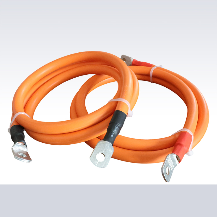
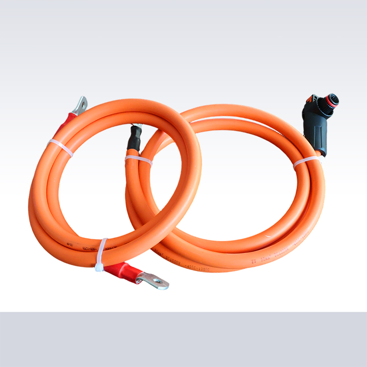
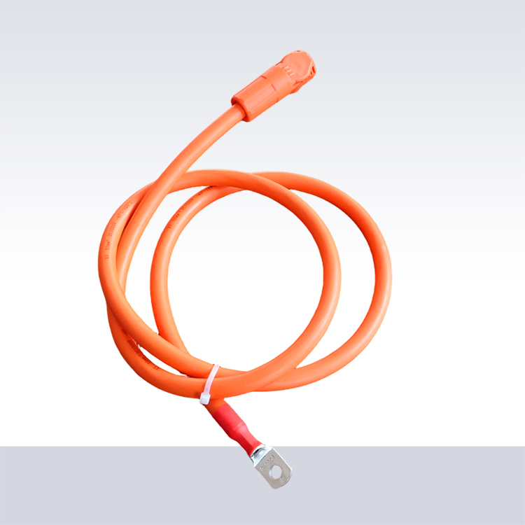
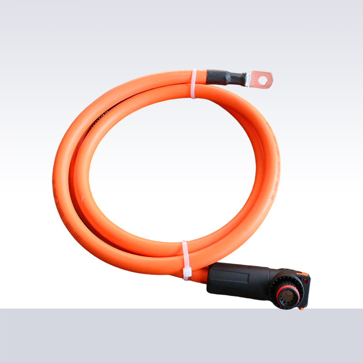
Orange jacketing has become standard for high-voltage EV cables. This color immediately identifies hazardous circuits to technicians and emergency responders. The warning function becomes critical during vehicle service or accident response.
Labels and markings provide additional information beyond color coding. Voltage ratings, current capacity, and manufacturer identification help service personnel understand what they're working with. Labels must survive the cable's service life without becoming unreadable.
Some manufacturers mold information directly into cable jackets rather than applying surface labels. This approach resists wear and degradation that might remove applied labels. A factory using molded markings demonstrates attention to long-term serviceability.
Emergency Response Considerations
First responders arriving at electric vehicle accidents face unfamiliar hazards. High-voltage cables that remain energized can injure rescue personnel attempting to extract occupants. Cable designs that facilitate safe emergency response protect both occupants and rescuers.
Emergency disconnect loops provide accessible points for severing high-voltage connections. These loops are designed for emergency cutting with standard rescue tools. Factory incorporation of emergency disconnect loops requires coordination with vehicle designers to identify appropriate locations.
Self-extinguishing insulation materials limit fire spread if cables ignite during an incident. Halogen-free compounds reduce toxic smoke production, improving survivability in enclosed spaces. Manufacturers specifying fire performance characteristics of their cables support emergency response planning.
References
Society of Automotive Engineers. SAE J2464: Electric and Hybrid Electric Vehicle Rechargeable Energy Storage System Safety. Warrendale: SAE; 2022.
National Fire Protection Association. NFPA 70E: Standard for Electrical Safety in the Workplace. Quincy: NFPA; 2024.
International Organization for Standardization. ISO 6469: Electrically propelled vehicles – Safety specifications. Geneva: ISO; 2019.






CONTACT
Email:525860526@qq.com
Whatsapp: +86 19933450664
TEL:+86 17803069333
WEB:https://www.haoshizai-solar.com
ADD:Dongyang Village, Daweihe Hui and Manchu Township, Wenan County, Langfang City, Hebei Province